REDUCING CO2 EMISSIONS IN BIOMASS POWER PLANTS USING THE INCAM MODEL
by Nor Aishah Saidina Amin
UTM-MIT Sustainable Cities Program, Institut Sultan Iskandar, Universiti Teknologi Malaysia Chemical Reaction Engineering Group, Faculty of Chemical and Energy Engineering, Universiti Teknologi Malaysia
Amin Talebian-Kalaikaleih Chemical Reaction Engineering Group, Faculty of Chemical and Energy Engineering, Universiti Teknologi Malaysia
Abstract
As the world’s second-largest palm oil producer and exporter, Malaysia could capitalize on its oil palm biomass waste for power generation. The emission factors from this renewable energy source are far lower than those from fossil fuels. This study applies an integrated carbon accounting and mitigation (INCAM) model to calculate the amount of CO2 emissions from three Malaysian biomass power plants. CO2 emissions released from biomass plants utilizing empty fruit bunch (EFB) and palm oil mill effluent (POME) as alternative fuels for powering steam and gas turbines were determined using the INCAM model. Each section emitting CO2 in the power plant—called a “carbon accounting center,” or CAC—was measured for its carbon profile (CP) and carbon index (CI) from each center. The carbon performance indicators (CPI) included electricity, fuel and water consumption, and solid waste and waste-water generation.
The carbon emission index (CEI) and carbon emission profile (CEP), based on total monthly carbon production, were determined across the CPIs. We developed various innovative strategies that resulted in a 20 to 90 percent reduction of CO2 emissions. The implementation of reduction strategies significantly reduced the CO2 emission levels. Based on the model, utilization of EFB and POME in the facilities could significantly reduce CO2 emissions.
Introduction
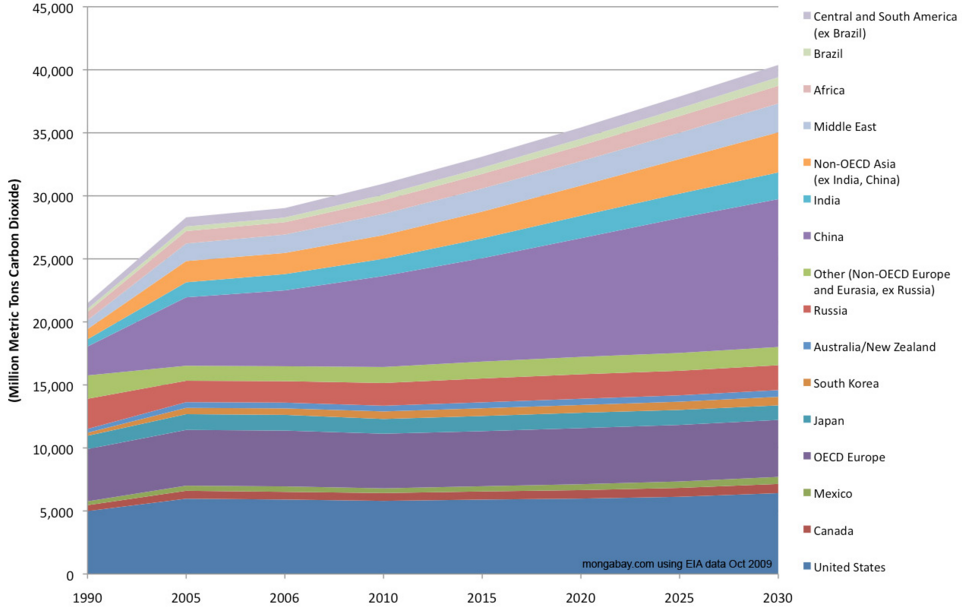
The rise in energy demand and the corresponding rise in greenhouse gas (GHG) emissions are causing climate change [1]. Figure 1 illustrates CO2 emissions by region from 1990 to 2030. CO2 emission levels are estimated to increase drastically for some regions of the world within 40 years. One key approach to addressing climate change is to replace fossil fuels with renewable energy for electricity production. Carbon emissions from renewable energy power plants are much lower than in fossil fuel production plants. Thus, reliance on fossil fuels to fulfill our energy demand without conservation efforts or increases in renewable energies will eventually lead to catastrophic global impacts. The development of non-fossil fuel energy sources is essential to reducing GHG, avoiding fossil fuel resource depletion, and coping with fluctuating fossil fuel prices [2-4]. CO2 emissions can be substantially reduced if biomass replaces fossil fuels to generate power. Indeed, unlike fossil fuels, burning renewable biomass is considered neutral in GHG emissions
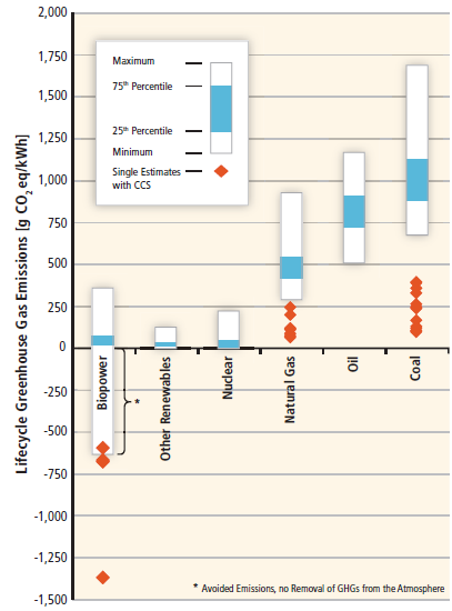
Trees take in carbon dioxide from the atmosphere and convert it into biomass. Whether they are burned or decompose naturally, they release the same amount of carbon dioxide [7]. The carbon that is released when biomass is burned is re-absorbed by other plants in their growth cycle. When fossil fuels are burned, however, they release CO2 that has been trapped for centuries, adding carbon to the atmosphere [8]. Figure 2 illustrates that renewable energies generate significantly lower GHG emissions compared with fossil fuels, including natural gas, oil, and coal.
Given Malaysia’s tropical biodiversity, conversion of waste (biomass) to energy is a promising approach to establishing sustainable energy production. Malaysia is ranked as the world’s second largest palm oil producer, next to Indonesia. Malaysia’s palm oil production exceeded 21.25 MMT in 2014, and has been increasing annually. Between 2009 and 2014, the acreage committed to Malaysia’s palm plantation increased from 4.7 to 5.4 million hectares, and crude palm oil production increased from 17.6 to 19.8 million tonnes [10].
The palm oil industry yields a tremendous amount of biomass waste, including fronds, trunks, mesocarp fibres, palm kernel shells, empty fruit bunches (EFB), and palm oil mill effluent (POME). This waste is a potential source for energy generation; however, only a small portion of it is currently used for steam and electricity generation [11–12]. A large fraction is simply burned or used as landfill [13]. Thus, government and industry are seeking ways to creatively utilize this massive palm-oil industry waste. For instance, heat from EFB combustion can be captured in a boiler to produce steam. EFB can be mulched or composted to aid in agriculture. POME, the voluminous liquid waste from the oil palm industry, is retained in ponds to reduce its toxicity and to release methane gas, and which can be used—if harvested properly—as valuable fuel for electricity, steam, or heat generation.
In accordance with global efforts to produce renewable energy and reduce CO2 emissions, Malaysia has developed strategic plans for increasing its share of renewable energy sources. Iskandar Malaysia, an innovative economic development zone in the southern state of Johor, has developed a Low Carbon Society Blueprint, called IM 2025, with a target to reduce carbon intensity by 58 percent from the 2005 carbon level by 2025. The Malaysian government designed a roadmap to make this economic development zone a “strong sustainable metropolis of international standing” by 2025, producing only 18.9 MtCO2qe GHG emissions, 40 percent lower than the projected amount [14].
Life cycle assessment (LCA) is a common tool used to study environmental impacts associated with all stages of a manufactured product's life cycle, from raw material extraction through materials processing, manufacture, distribution, use, repair and maintenance, and disposal or recycling. For example, the environmental impacts in the different parts of the palm oil supply chain have been identified using LCA in nurseries [15], fresh fruit bunches [16], crude palm oil [17], and biochar from empty fruit bunches [18]. LCA is also used for palm kernel oil [19], refined palm oil [20], and palm diesel [21]. Alternatively, a simpler integrated carbon accounting model (INCAM) considers direct and indirect carbon emissions [22].
The main objective of this paper is to apply the INCAM model to determine the amount of CO2 emissions from three Malaysian biomass electric power plants. This paper analyzes three case studies that use oil palm waste to generate electricity. The first, Bio-Xcell Sdn. Bhd.—a central utility facility situated in Iskandar Malaysia—uses EFB to produce steam. The other two companies, Kulim Gp Oil Palm Mill and Ronser Bio-Gas Sdn. Bhd, use POME as an alternative fuel for firing gas turbines to produce electricity. These three companies implemented various innovative strategies to reduce CO2 emissions. The findings from our study provide basic, useful data for developing renewable energy policies to lower CO2 emissions from the industrial sectors in Iskandar Malaysia.
Methods
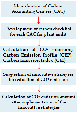
The INCAM model determines the reduction in CO2 emissions levels as illustrated in the flowchart in Figure 3. Initially, each process is divided into smaller scoping units known as “carbon accounting centers” (CACs) for easy monitoring of CO2 emission levels. Next, a carbon checklist is developed to identify carbon emission sources for each division, and a plant audit is performed. Five main emission contributors—fuel, water, and electricity consumption, and wastewater and solid-waste generation—are identified as Carbon Performance Indicators (CPI). The Carbon Emission Index (CEI) for each CPI is based on CO2 emission factors [22–23]. The CPI with the highest emissions is identified as the hotspot based on the Carbon Emission Profile (CEP). After the hotspot is identified, innovative strategies are suggested to reduce carbon emissions. The carbon emissions are again calculated after the implementation of innovative strategies to reduce carbon emissions. Finally, after measuring the carbon emission reduction amounts in each plant, all three plants’ carbon emission reductions are compared to identify the plant with the highest reduction in carbon emission.
Case Studies
The effectiveness of the INCAM methodology is evaluated in our three subject companies: Bio-Xcell, Kulim Group Oil Palm Mill, and Ronser Bio-Gas.
Bio-Xcell, located in Nusajaya, Iskandar Malaysia, uses EFB as fuel for steam production. The steam is supplied to other nearby power plants for generating heat and electricity. The Bio Xcell plant has three divisions: steam generation, wastewater treatment, and chiller plants.
The Kulim Group Oil Palm Mill is situated in Kulai, Johor. In this facility, POME retained in ponds releases methane gas and electricity is generated from combusting methane in a gas engine. Biogas or methane from the POME pond is trapped, conditioned, and scrubbed before combustion.
The third case company, Ronser Bio-gas, located in Kuala Lumpur, also converts POME to methane gas to generate electricity used for powering its mill. Table 1 lists the production outputs of these three power plants.
Process description
A detailed flow process for all three plants is described in the following sections based on the information supplied by each company.
Bio-Xcell
Figure 4a depicts the flow process of the Bio-Xcell facility. The main divisions are the steam generation plant (boilers, biomass storage, and LPG farm), water pre-treatment plant, and chiller plant, as depicted in Scheme 1a. Two bi-water tube boilers are fueled by biomass, and a fire tube boiler uses LPG. Raw water is pre-treated in the water pre-treatment plant to ensure high-quality steam. In the LPG farm, the liquefied petroleum gas is treated and vaporized before entering the boiler. The biomass is stored in a storehouse and carried on a conveyer belt into the boiler.
Three types of fuel consumption data were collected—diesel (on-site transportation), LPG (fire-tube boiler) and EFB (water-tube boiler). The electricity generation data for each section was not available, but the general electricity consumption data for the entire plant is assumed to be from the chiller plant. The feedstock supplied to Bio-Xcell is wet EFB with about 5-7 percent moisture [24]. According to our calculations, an estimated 5 percent of water and solid fuel consumption become wastewater and solid waste. Based on our site observations and discussions with the plant engineers, we calculated a 5 percent solid waste generation, since EFB combusts well, and a relatively small amount of ash and coke remained at the end of process.
Kulim Group and Ronser Bio-gas companies
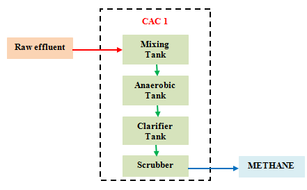
The flow process of the Kulim Group and Ronser Bio-gas plants are described in Figure 4b and 1c, respectively. The carbon accounting centre or main section considered in this study is the methane gas production process, or CAC 1. In detail, raw POME is fed to the mixing tank for pre-treatment, then sent to the anaerobic tank for microbiological processing, which included:
- Hydrolysis (complex molecules are broken down into simple molecules);
- Acidogenesis (production of various types of acids, and ammonia, CO2, H2S, and H2);
- Acetogenesis (production of acetic acid, CO2, and H2);
- Methanogenesis (the last stage for methane gas production).
Assessment of carbon in each unit
The steps needed to identify the carbon accounting centers, determine total monthly carbon emissions, calculate the CEIs, and reduce CO2 emissions are described here. Several strategies are considered to reduce carbon emissions across the CPIs.
STEP 1: Identification of CAC Bio-Xcell central facility
Three CAC breakdowns are used in this study. CAC1 represents the steam-generation process, which includes three sub-CACs of biomass storage, along with the LPG farm and boilers. CAC2 and CAC3 represent the water pretreatment and chiller plants.
Kulim Group and Ronser Bio-gas facilities
For this case study, only one CAC breakdown was performed. CAC1 represents the methane production process.
STEP 2: Carbon checklist development and plant audit
The carbon emission sources in each CAC are identified in this step. Table 2 lists the various carbon emission sources for each CAC. The audit process involved a site visit and data collection of the companies’ utility bills, procurement reports and domestic waste reports. The audit process provided significant information about the monthly consumption and generation of five carbon performance indicators (CPI)—fuel, water, electricity consumption, wastewater, and solid waste generation. Those values, listed in Table 3, were subsequently used for carbon emission analysis in the next step.
STEP 3: Establish carbon emission profile (CEP) and carbon emission index (CEI)
Table 4 summarizes the carbon profile (CP) and carbon index (CI) of each CAC subsection. The highest total monthly CO2 emission is released by the boilers and POME consumption in the EFB and POME utilization processes, respectively. Thus, the steam generation in the boilers and methane gas generation process are identified as the hotspots in these case studies. The first and most important information needed was the amount of CO2 emissions for each CPI. The emission factors related to each CPI were collected from the literature [22-23]. Meanwhile, the monthly carbon emission equivalent (MCEE) was calculated by multiplying the CO2 emissions and amounts of each CPI’s consumption or generation in a month (Eq. 1). The carbon profile (CP) and carbon index (CI) for each CAC were determined by eqs (2-3). The CEP and CEI for each CPI were calculated with eqs (4-5).
Monthly Carbon Emission Equivalent (MCEE) =
Monthly Consumption or Generation ×
Emission Factor (1)
CAC carbon profile (CP) =
Total monthly CO2 of each CAC ×100 (2)
Total monthly CO2 equivalent (tCO2e)
CAC carbon index (CI) =
Total monthly CO2 of each CAC (3)
Total monthly of production (tone) in a month
Carbon emission profile (CEP) =
Total monthly CO2 of each CPI ×100 (4)
Total monthly CO2 equivalent (tCO2e)
Carbon emission index (CEI) =
Total monthly CO2 of each CPI (5)
Total amount of production (tone) in a month
STEP 4: Recommended strategies for carbon emission reduction
Table 5 summarizes the recommended strategies for reducing CO2 emissions in all three cases. At Bio-Xcell, we recommended decreasing fresh water intake to reduce CO2 emissions. Recycled water could be utilized in boilers, water treatment, and chiller plants in CAC 1, CAC 2, and CAC3, respectively. Next, we recommended using natural gas instead of diesel fuel in the biomass storage section (CAC1), which could significantly reduce CO2 emissions.
We also recommended using higher-efficiency cooling tools to reduce electricity consumption [22]. Utilization of briquette EFB as a solid fuel instead of shredded and pellet EFB could increase the energy content of EFB by increasing the fuel calorific value (CV) [25]. Also, we recommended improvements in the furnace design and the draft calibrations to help ensure complete combustion of the biomass [26]. The difference between monthly carbon emissions of each CPI before and after implementation of reduction strategies as “CPI reduction (%)” is reported in Table 5. In fact, about 18.2 percent to 25 percent of emission reductions across the CPIs were achieved due to the implementation of the recommended strategies.
In the Kulim and Ronser plants, the target was for as much POME as possible to be used to generate a steady supply of methane. Thus, the amount of POME consumption should not be decreased when implementing the CPI reduction strategy. However, application of a highly efficient anaerobic reactor could increase methane production; thus, the first strategy to reduce current CO2 emission was to decrease fresh and wastewater consumption by utilizing recycled water [22]. Next, the application of cooling tools, which require less energy, was suggested for significant reduction of electricity consumption. The Kulim and Ronser plants produced sludge as waste. Since about 98 percent of the sludge is water, water recycling could significantly reduce the amount of solid waste. Table 5 shows the difference between monthly carbon emissions of each CPI before and after implementation of reduction strategies as “CPI reduction (%).” About a 20 to 90 percent reduction of various CPIs are attributed to the implementation of the recommended strategies.
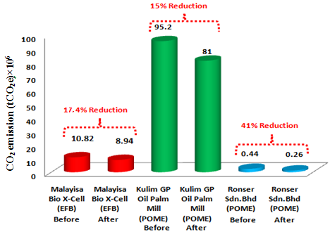
Data for CI of each CAC following the reduction strategies are summarized in Table 6. Initially, the CO2 emissions in the Bio-Xcell, Kulim, and Ronser plants were 10.82×10⁶, 9.52×10⁷, and 4.4×10⁵ tCO2e, respectively; however, after emission reduction strategies were implemented, CO2 emissions decreased to 8.94×10⁶, 8.1×10⁷, 2.6×10⁵ tCO2e, respectively. The total monthly CO2 emissions related to the three case studies before and after reduction strategies were implemented appear in Figure 5, with 17.4 percent, 15 percent, and 41 percent reduction for Bio-Xcell, Kulim and Ronser, respectively.
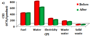
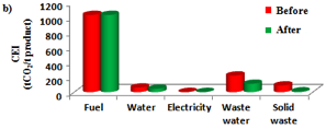
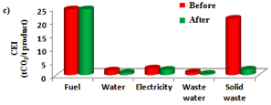
The bar charts in Figure 6 compare the CEIs of the three plants before and after the implementation of reduction strategies. CEI is the main indicator of whether the strategies to reduce CO2 emissions were successful. In general, all the CEIs across the CPI for the three companies decreased. For example, in Bio-Xcell, the CEI for fuel and water significantly decreased after the reduction strategies were implemented. In addition, profound reduction of solid waste at Ronser Bio-gas also directly resulted from the reduction strategies.
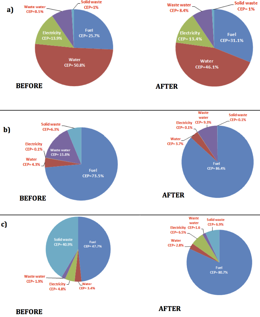
Figure 7 presents six pie charts of the CEP of the three cases before and after the reduction strategies. The hot spot in each case study is highlighted in the pie charts. Fuel and water consumption are the hot spots for the Bio-Xcell companies due to the largest CEP. POME consumption and waste water generation are the hot spots for Kulim, and POME consumption and solid waste generation are the hotspots for Ronser Bio-gas. Nonetheless, the CEP for fuel consumption significantly increased from 47.7 percent to 80.7 percent. Notably, the solid waste generation declined from 40.9 percent to 6.9 percent (90 percent reduction), which suggests that the reduction strategies were effective.
Comparison of CO2 reduction: EFB and POME vs. coal and diesel
The CO2 emissions from the different fuels are compared in this section. According to the EU Directive, CO2 or GHG emissions reduction savings are calculated by Eq. (6) [27]:
Percentage of CO2 reduction =
(CO2 emission of fossil fuel consumption –
CO2 emission of POME consumption) /
CO2 emission of fossil fuel consumption (6)
CO2 emissions from palm oil waste were lower compared to fossil fuels. Table 7 reveals that EFB and POME combustion could reduce CO2 emissions by 57–65 percent and 85.8–89.2 percent, respectively, compared to coal and diesel. Olisa and Kotingo [26] who compared the utilization of EFB and natural gas in power generation, confirmed that EFB utilization was more economical and had significant advantages. Agricultural waste materials—such as EFB or POME—are abundantly available as renewable fuels for power generation. Utilization of these wastes translates into cheaper feedstock for power generation. Furthermore, significant reduction of capital costs, landfills, GHG emissions from EFB composting, and POME ponds suggest that investment in renewable energy is economically viable [10, 28].
Conclusions and recommendations
This study used the carbon accounting and mitigation method (INCAM) to assess ways to reduce CO2 emissions from three Malaysian power plants, and found that all three plants could decrease their fuel and water consumption expenses by replacing fossil fuels with EFB and POME biomass. Additionally, the carbon emission indexes across the carbon performance indicators were substantially reduced by replacing fossil fuels with biomass fuels. By utilizing EFB or POME in their power plants, total monthly CO2 emissions decreased by 17.4 percent, 15 percent, and 41 percent, respectively, for Bio-Xcell, Kulim and Ronser. By replacing coal and crude oil with EFB and POME, the three firms clearly lowered their CO2 emissions.
This study’s findings could improve Malaysia’s regional position in the renewable energy technology market, considering that palm trees—the raw materials for EFB and POME—are native to Malaysia and a major agricultural crop.
In addition, the findings from this study can guide companies aiming to invest in or establish a power plant using organic waste products from the oil palm industry. One key recommendation is that these firms should build power plants near an oil palm mill. The private sector should provide proper access to roads to the mills. The government should provide subsidies to enterprises that replace fossil fuels with biomass for power generation and for vehicles, and also sponsor awareness programs for the local communities.
Strong incentives have been approved by the Malaysian government for pioneer companies focused on renewable energy (RE) and energy efficiency (EE)—such as a 70-100 percent income tax exception—to expand the implementation of renewable energy in Malaysia. However, the majority of incentives in this field are allocated to pioneer companies that have worked during the last 10 years in waste management programs. New incentives are crucial to attract local and international companies for investment in this field, due to their significant impacts on the economy and environment.
Bio-Xcell is the first model site for steam production from EFB in IM. Bio-Xcell is a good model for other industrial regions of Malaysia to reduce fossil fuel utilization in electricity generation. Investment and utilization of one of the most valuable local waste products in the energy-generation process could significantly improve the economy, and eliminate various environmental concerns in Iskandar Malaysia.
Acknowledgements
The authors would like to thank the MIT-UTM Sustainable City Program under the Institut Sultan Iskandar, Universiti Teknologi Malaysia.
References
[1] Kerdsuwan, S., and K. Laohalidanond. 2011. Renewable Energy from Palm Oil Empty Fruit Bunch, Renewable Energy – Trends and Applications, Dr. Majid Nayeripour (Ed.), ISBN: 978-953-307-939-4, InTech, Available from: http://www.intechopen.com/books/renewable-energy-trends-andapplications/ renewable-energy-from-palm-oil-empty-fruit-bunchPaper Keyword 2014; International Energy Agency (IEA), www.worldenergyoutlook.org, www.iea.org/books.
[2] Talebian-Kiakalaieh, A., N.A.S. Amin., H.Mazaheri. 2013. A review on novel processes of biodiesel production from waste cooking oil. Applied Energy, 104, 683.
[3] Maceiras, R., M., Rodríguez, A. Cancela, S.Urréjola, A. Sánchez. 2011. Macroalgae: raw material for biodiesel production. Applied Energy 88(10): 3318–23.
[4] Santori, G., G. D. Nicola., M. Moglie., F. Polonara. 2012. A review analyzing the industrial biodiesel production practice starting from vegetable oil refining. Applied Energy 92: 109–32.
[5] Ibrahim, A. 2016. Adapting to Climate Change, New Straits Times Online, http://www.nst.com.my/news/2016/03/132559/adapting-climate-change
[6] World CO2 emission level by region between 1990 and 2030 (Energy Information Administration (EIA), 2009), http://rainforests.mongabay.com/09-carbon_emissions.html
[7] Cho, R. 2011. Is biomass really renewable? http://blogs.ei.columbia.edu/2011/08/18/is-biomass-really-renewable. Earth Institue, Columbia University, 18thAgust.
[8] U.S. Department of Energy, Biomass Power Association, http://www.reenergyholdings.com/renewable-energy/biomass-faqs, ReEnergy Holding LLC, 2011.
[9] Moomaw W, F. Yamba., L. Kamimoto., L. Maurice., J. Nyboer., K. Urama., T. Weir. 2011. Introduction In IPCC special report on renewable energy sources and climate change mitigation [Edenhofer O, Pichs-Madruga R, Sokona Y, Seyboth K, Matschoss P, Kadner S, Zwickel T, Eickemeier P, Hansen G, Schlomer S, von Stechow C], Cambridge University Press, Cambridge, United Kingdom and New York, NY, USA.
[10] Aditiya, H. B., W. T. Chong., T. M. J. Mahlia., A. H. Sebayang., M. A. Berawi., H. Nur. 2015. Second generation bioethanol potential from selected Malaysia’s biodiversity biomasses: A review. Waste Management, DOI: http://dx.doi.org.ezproxy.canberra.edu.au/10.1016/j.wasman.2015.07.031.
[11] Mahlia, T. M. I., M. Z. Abdulmuin., T. M. I. Alamsyah., D. Mukhlishien. 2003. Dynamic Modeling and Simulation of a Palm Wastes Boiler. Renewable Energy 28: 1235–1256.
[12] De Souza, S., S. Pacca., M. De Avila., J. Borges. 2010. Greenhouse Gas Emissions and Energy Balance of Palm Oil Biofuel. Renewable Energy. 35: 2552–2561.
[13] Lahijani, P.,and Z. A. Zainal. 2011. Gasification of Palm Empty Fruit Bunch in a Bubbling Fluidized Bed: A Performance and Agglomeration Study. Bioresource Technology.102: 2068–2076.
[14] Low Carbon Society Blueprint for Iskandar Malaysia 2025—Summary for Policymakers. 2014 UTM-Low Carbon Asia Research Centre. Third edition November 2014.
[15] Halimah, M., H. Zulkifli., S. Vijaya., Y. A. Tan., C. W. Puah., C. L. Chong., and Y. M. Choo. 2010. Life cycle assessment of oil palm seedling production (Part 1) .J. Oil Palm Res, 22,876-886.
[16] Zulkifli H., M. Halimah., K. W. Chan., Y. M. Choo., W. Mohd. Basri. 2010. Life cycle assessment for oil palm fresh fruit bunch production from continued land use for oil palm planted on mineral soil (Part 2). J. Oil Palm Res, 22,877-894.
[17] Vijaya S., Y. M. Choo., M. Halimah., H. Zulkifli., Y. A. Tan., C. W. Puah. 2010a. Life cycle assessment of crude palm oil (Part 3) .J. Oil Palm Res, 22,895-903.
[18] Harsono, S. S., P. Grundman., L. H. Lau., A. Hanse., M. A. M. Salleh., A. Meyer-Aurich., A. Idris., T. I. M. Ghazi. 2013. Energy balances, greenhouse gas emissions and economics of biochar production from palm oil empty fruit bunches. Resources, Conservation and Recycling, 77: 108-115.
[19] Vijaya S., Y. M. Choo., M. Halimah., H. Zulkifli., Y. A. Tan., C. W. Puah. 2010b. Life cycle assessment of crude palm kernel oil (Part 3a) .J. Oil Palm Res, 22, 904-912.
[20] Tan Y.A., M. Halimah., H. Zulkifli., S. Vijaya., C. W. Puah., C. L. Chong., A. N. Ma., Y. M. Choo. 2010. Life cycle assessment of refined palm oil production and fractionation (Part 4) .J. Oil Palm Res, 22, 913-926.
[21] Puah C.W., Y. M. Choo., A. N. Ma. 2010. Life cycle assessment for the production and use of palm biodiesel (Part 5) .J. Oil Palm Res, 22, 927-933.
[22] Hashim, H., M. R. Ramlan., L. J. Shiun., H. C. Siong., H. Kamyab., M. Z. A. Majid., C. T. Lee. 2015. An Integrated Carbon Accounting and Mitigation Framework for Greening the Industry. Energy Procedia, 75, 2992-2998.
[23] The Climate Registry. 2014: https://http://www.theclimateregistry.org//2014/02/2014-Climate-Registry... on 22 December 2014.
[24] Abdullah, N., and F. Sulaiman. 2013. Biomass Now—Sustainable growth and use. INTECH,under CC BY 3.0 license, ISBN 978-953-51-1105-4,DOI: 10.5772/55302.
[25] Yuhazri, M.Y., H. Sihombing., S. H. Yahaya., M. R. Said., U. Nirmal., S. Lau., P. P. Tom. 2012. Solid fuel from empty fruit bunch fiber and waste papers part 3: ash content from combustion test. Global Engineers & Technologists Review, 2 (3).
[26] Olisa, Y. P., and K. W. Kotingo. 2014. Utilization of palm empty fruit bunch (PEFB) as solid fuel for steam boiler. European Journal of Engineering and Technology. 2(2).
[27] Zutphen, J. M. V., and R. A. Wijbrans. 2011. LCA GHG emissions in production and combustion of Malaysian palm oil biodiesel. Journal of Oil Palm & the Environment, 2: 86-92.
[28] Sivasangar, S., Z. Zainal., A. Salmiaton., Y. H. Taufiq-Yap. 2015. Supercritical water gasification of empty fruit bunches from oil palm for hydrogen production. Fuel, 143, 563-569.
Notes
Data on solid waste and waste water production from the steam generation plant were not available.
